ROHR: BACKGROUND INFORMATION THE BART RAPID TRANSIT VEHICLE
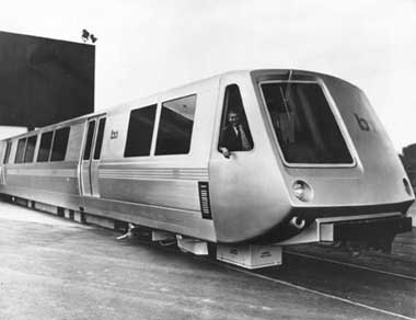
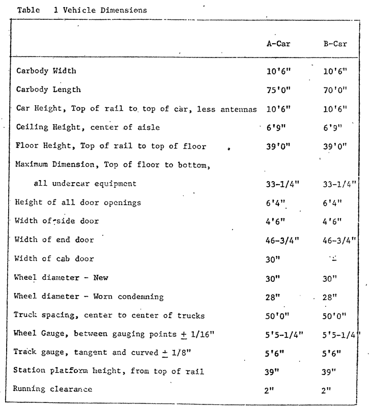
Rohr is building 450 vehicles for BART under a $143 million in contracts awarded since July 1969. Cars with attendant's cabs ("A" cars), each 75 feet long, are placed on each end of the BART trains. Cars 70 feet long are located in the middle of the trains ("B" cars). The trains are from two to ten cars long, depending on the passenger capacity required.
Using a systems management concept common to the aerospace industry, Rohr designed the car to meet a set of performance requirements rather than to fit existing available components. The car was initially designed at the systems engineering level to perform certain functions, i. e., to ride properly on a given track; to accelerate at a certain rate; to maintain a high degree of reliability; and perform to stringent safety requirements. The vehicle system, as a whole, was broken down into subsystems and components. The trucks had to be designed to operate on a given track. The propulsion system had to be designed to meet speed performance requirements. Systems integration became a major consideration and resulted in formal documentation, to establish just what would happen when a component is interfaced with another component.
The BART cars are being assembled by methods new to the rapid transit industry. Individual components are combined into sub-assemblies which are inspected and tested, and then incorporated into major assemblies. Each major assembly is then inspected and tested before going into final assembly. Finally, the completed vehicles are subjected to
a series of tests for a step-by-step checkout of all systems.
Rohr has employed engineering and manufacturing technology in designing and building the cars to provide maximum passenger comfort and safety, as well as improved reliability and ease of maintenance. The cars have wall-to-wall carpeting, which reduces noise levels and provides a more comfortable riding atmosphere. Temperature and humidity are controlled by a multi-zone air conditioning system that provides a constant flow of fresh air without the presence of drafts. BART passengers will ride in much quieter surroundings than commuters in private automobiles.
The cars are supported on eight air cushion bellows (four per truck) which provide a smooth, comfortable ride, even at top speeds. Since the air bellows absorb more vibration than mechanical springs, roadbed irregularities go virtually unnoticed. The loam-padded seats are more comparable to living room chairs than to the ones usually, bond in transit cars. Not only are they more comfortable than other seats, they are cantilevered; i. e., suspended from the cars' side walls without standard pedestal supports. Elimination of the pedestal increases legroom and results in easier maintenance of car interior.
Cantilevered seats are possible because the BART cars utilize a "semi-monocoque" design in which the body is integral with the chassis and bears most of the loads. Monocoque design is used in construction of jet aircraft to achieve maximum strength at minimum weight.
The cars are built of aluminum extrusions, some of which run the full length of the vehicles. The result is a smooth, durable surface with no visible rivets or fasteners. Attendant's cabs on the "A" cars are one-piece fiberglass with no seams, similar to Modern boat hulls. The windshield is made of high-impact glass similar to that used on commercial aircraft.
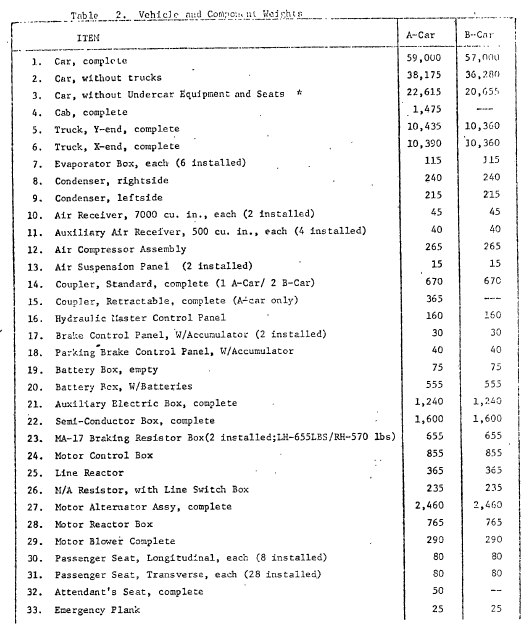
The BART propulsion system is the most advanced ever installed on transit vehicles in this country. It operates so smoothly that passengers have virtually no sensation of starting and stopping. The system will accelerate trains from a standstill to 50 miles-per-hour in 20 seconds and decelerate them from the 80 miles-per-hour top speed to a station stop in 27 seconds. The cars are among the lightest in the world. The light weight reduces power requirements. Even the wheels, with aluminum centers and steel rims, are light in weight.
Other improvements have been incorporated in the doors and electrical systems. A new Mechanism prevents "gaps" in the doors, eliminating drafts and rattling. Shielding of the electrical systems prevents interference with television and radio reception as the cars pass. Many of the innovations in the design of the vehicles were developed by Rohr. Among these are the cantilevered seats, improvements in the door hanger system, the attendant's cab, and the extruded aluminum construction.
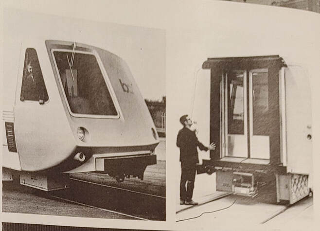
BART vehicles are built in two configurations identified as "A" cars and "B" cars. The two configurations are identical in all respects except that an "A" car has an Attendant's cab mounted to its front. The aft end of each configuration is referred to as the X-end and the forward end as the Y-end of the vehicle. An operational train consists of a minimum of two "A" cars mated back-to-back. Increased passenger capacity is attained by coupling from one to eight "B" cars between the two "A" cars.
Train control is accomplished through vital train lines running throughout the length of the train, and connected through the electrical portion of each car end coupler. The train is operated or controlled in one of three modes-
(1) AUTOMATIC - The train is controlled from the remote operational control center (OCC) by signals received through vehicle antennas and route relay antennas. Train speed, braking, stopping and door operations are automatically controlled in this mode. Train speed can be varied between 0 and 80 MPH in the automatic mode.
(2) ROAD MANUAL - The train is controlled by the attendant from the cab through the operation of the attendant's control level. Train speed can be varied between 0 and 25 MPH in the road manual mode. This mode is used when a malfunction occurs in the Automatic Train Control (ATC) System to move the train on the mainline tracks.
(3) YARD MANUAL - The train is controlled by the attendant from the cab. This mode is used primarily within the District Yard Service Areas. The maximum speed obtainable is 10 MPH.
Car Body Structure
The car body is an integrated structure, reinforced in areas subject to high stress by the use of aluminum extrusions, the car sidewalls are designed to carry the car weight throughout the span of the car. The floor beams and roof are riveted to the sidewalls, completing the integrated car body structure. To compensate for the openings of the side
doors, special door frames are installed into the sidewall, thereby, insuring the continuity of sidewall strength. The Roof Panel is constructed of 3003 H14 aluminum alloy sandwiched with 300F Foam. The outer skin is a single piece running the full length of the car. Roof bows are contained within the structure. This sandwich structure is attached to four longitudinal stringers extending the full length of the car, two of which provide support for any future strap hangar applications. The roof panel is capable of supporting a 250 pound man. At the outer edge of the roof, and extending the length of the car, three inch by two inch deep rain gutters to prevent rain run-off down the sides of the car These rain gutters are open-ended, with lip troughs, to provide drainage over the ends. The roof has an inner liner that carries the interior car lighting and speakers. The liner is made of molded fiberglass, riveted to the roof panel, and made, in five sections. The liners, by removing the rivets, can be lowered from the roof panel, but due to their size are not removable from the interior of the car, without a major end-panel removal.
The end panels are of a unitized construction, riveted to the, roof panel and sidewall. The X-end panel houses the car control panel and the door relay panel.
The floor beams are interlaced with intercostal members to provide a means of suspending various undercar components, and transferring the weight of the undercar components to the sidewalls. The bolster serves to anchor the trucks to the car body, and to provide a pivot axis capable of allowing truck pivot under the car for all calculated BART rail curves. The underside of the bolster has an impregnated surface of Teflon to reduce friction between the truck and the bolster.
The floor beams are interlaced with intercostal members to provide a means of suspending various undercar components, and transferring the weight of the undercar components to the sidewalls. The bolster serves to anchor the trucks to the car body, and to provide a pivot axis capable of allowing truck pivot under the car for all calculated BART rail curves. The underside of the bolster has an impregnated surface of Teflon to reduce friction between the truck and the bolster.
Another function of the bolster is to allow air to enter the air suspension bags of the trucks, by positioning the air hose into the air suspension bags for all -calculated truck pivot movement. The bolster is riveted to the, car sidewalls and transfers the acceleration and deceleration efforts from the truck to the car body. The bolster also serves as the anchor for the car end-sill. The end-sills are mounted to the bolsters with twelve special 3/8 inch bolts, capable of withstanding normal car buffing, that will shear under extreme buffing to reduce car-telescopic damage. The end-sill also provides a firm anchor for the car coupler. The tension-compression forces created during vehicle movement are transferred through the inter-car couplers.
Completing the floor structure are six floor panels (cars up to Number 35 contain 14), riveted to the sidewall frame and the floor beams to complete the integrated circle around the car body. The floor panels are a metal sandwich structure, with the outer skins made of 6061-T6 aluminum, and a core composed of two inch thick polystyrene foam. The outer skins, and foam core are bonded together with FR8550 epoxy. With the exception of the windows, the car is completely insulated. The side wall insulation is such that it provides air passageways to direct conditioned air upward at the bottom of the side windows and acts as a defroster on cold days.
The X-end of each A-car configuration and each end of the B-car configuration are provided with an intercar closure. The closure provides an enclosed passageway between vehicles. The closure section consists of buffer faceplates extended from the car end sill by elastomeric shear springs capable of both angular and longitudinal motion. An elastomeric diaphragm is located above the faceplates. The diaphragm on one vehicle contacts the diaphragm on the adjoining coupled car during train operation. A drain trough is located on the top portion of the diaphragm to divert water away from the mating surfaces of the two diaphragms.
The Y-end of an A-car is mounted with a cab riveted to the sidewalls and roof panel. The, cab is made of foam sandwiched fiberglass to form an insulated compartment to house the various control components and provide the train attendant with an isolated environment. The cab side windows can be swung open to afford an external view, of the train. The cab does not rest upon the end-sill, thereby eliminating any vibration that may emanate from the end-sill, or undercar structure.
Sidewall windows located within the passenger compartments of each vehicle configuration are 1/4 inch green tinted safety glass and cannot be opened. The end door windows are single glazed, clear and cannot be opened. The cab side windows are similar to the sidewall windows but are contoured and can be swung inward to open. The cab windshield is made of 1 inch thick, green tinted, laminated safety glass fixed in position. The cab windshield will withstand a pressure of fifty pounds/foot force which is equal to a 175 MPH windload. All windows are installed from the exterior of the vehicle.
Four types of seats are used on the BART vehicles. The four types are differentiated only by configuration. The seat backs are of a fiberglass reinforced plastic laminate. The seats are covered with vinyl and plastic coated nylon fabric.
The double sliding end doors are constructed of aluminum with a foam core. The doors are suspended by door hangers that house rolling ball bearing races riding on the overhead rails. The bottom of the doors are retained in a threshold guide slot, and at the last inch of door closure, are cammed outward to seal the door recesses. Sealing between the sliding door mating surfaces is by two neoprene extrusions and sealing around the door edges is by typical sealing strips bonded to an aluminum strip and cap-screwed to the door frame-, or to the bottom of the door. The door rails are surrounded by a 1/8” cable riding on two pulleys, mounted at the extreme of the door rails. The cable causes both sliding doors to travel in opposite directions when one or both doors are manually opened.
The side doors are of foam core construction, reinforced internally for strength as well as providing attachments for door hardware and operating arms. The doors are constructed of aluminum alloy, with an exterior brush finish; matching the exterior car skin, and with the interior finish coated with alumilite (Alcoa 215C3) to present a smooth surface.
Vehicle Sub-Systems
The BART vehicle contains five functional interrelated subsystems that provide electrical power, propulsion, braking, suspension and air comfort. These systems are common to both A-car and B-car configurations. The A-car is controlled from the Attendant's Control Panel in the forward direction and from a Hostling Panel in the X-End of the car for travel in the opposite direction. The B-Car can be controlled, from a Hostling Panel at either end of the car, for movement in that direction.
Whether the subsystems are controlled by any one of the control inputs is contingent upon the settings of the controls within a vehicle or train of vehicles. Control of a train composed of two A-cars and a maximum of eight B-cars, is exercised by the setting of a single control unit (Attendant's Control Console) of the lead A-car which provides control signals via the tramlines to the other vehicles within the train. Diagnostic Test Equipment is provided for testing of the above subsystems.
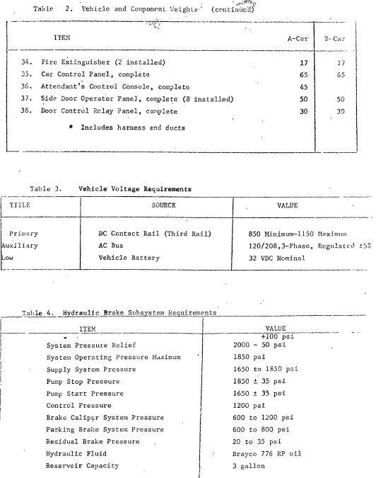
The 1,000 V DC high current feeds from the third rail shoe to the Auxiliary Power Subsystem by way of the Auxiliary Box. 1000 V high voltage passes to the line Switch Box, Line Reactor, and into the Motor Control Box. The Motor Alternator operates in conjunction with the Aux. Box to generate the vehicle's basic 32 V DC and 3 Φ 120-208 V AC power sources. The 32 volt source charges the vehicle's battery, which, in turn, assures 32 V DC is present for such vehicle electronic devices as relays, lighting indicators, and control PC board circuits. The Motor Alternator function is to generate the basic 3 Φ 120/208 V AC for other vehicle electrical devices and also furnish mechanical drive for the Air Comfort Subsystem's compressor assembly, 120 V AC is available at terminals to which the 3 Φ 208 V AC is routed.
Assemblies grouped within the propulsion Subsystem are: the Line Switch Box, the Line Filter, the Line Reactor, the Motor Control Box, the Semiconductor Box, the Propulsion Blower, and the Braking Resistors. Key control inputs are the ATC control or “P” signal -- an analog current signal that commands the Semiconductor box to send out subcommand signals which operate Motor Control Box interlocks that in turn control subsystem braking and motoring circuits; the BRK Signal -- a "P" signal with a limited speed range; the Yard Manual Control Signal -- a simulated "P" signal capable of commanding low speed motoring for a limited time; and the Direction Signal. Outputs from the Semiconductor box to the Friction Brake Subsystem are the Brake Command Signal; the Dynamic Brake Signal; and the Manual Parking Signal. Two additional outputs from the Semiconductor Box are contained in the 1, 000 V DC Motoring and 1,000 V DC Braking circuits which pass high currents to and from the traction motors. Two groups of signal inputs (one consisting of speed signals from the Truck Subsystem speed sensors and the other load weight signals from the Air Suspension Subsystem) feedback signals to the Semiconductor Box which help it to give appropriate commands to associated vehicle subsystems. The Propulsion Blower unit uses a motor requiring 3 Φ 208 V AC ouput and functions to cool the Propulsion Subsystem Semiconductor Box and Braking Resistor Assemblies. The pneumatic lines to the Line Switch Box and the Motor Control Box furnish the air required to drive the electro-pneumatic switches located within these assemblies.
The Friction Brake Subsystem consists of electro-hydraulic units that control the Brake disc assemblies located in the Truck Subsystem. The two groups of signals, which are control inputs to the friction brake electro-hydraulic units, are control signals arriving via the logic tray of the Semiconductor Box Assembly and speed signals from the speed sensors which are mounted on the truck assembly gear units.
Connections between the Air Conditioning Subsystem and the remaining vehicle subsystems are of a power input nature. 1,000 V DC low current input is taken directly from the line switch box, 3 Φ 120/208 V AC input is supplied by the Auxiliary Power Subsystem, and the motor drive input for the Subsystem's air compressor is taken directly from the Motor Alternator assembly. Thermostat positions within the vehicle cause the subsystem to be of a self-regulating nature once it is energized.
There are three general links between the Air Suspension Subsystem and other vehicle subsystems. The standard power sources from the Auxiliary Power Subsystem; the group of load weight signals feeding to the Semiconductor Box; and the pneumatic connections to the Air Spring Assemblies.
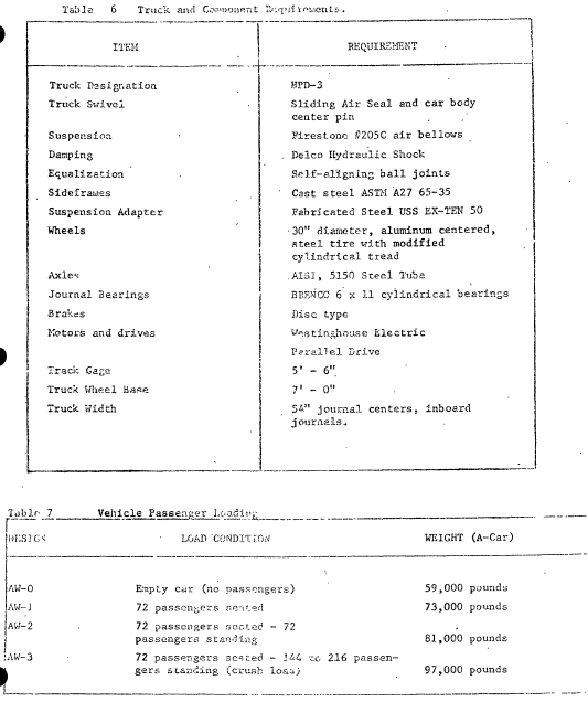
Each truck of the vehicle is made up, of mechanical, electrical, pneumatic and hydraulic components controlled by electronics contained in the previously discussed subsystems. The truck frame is a steel casting. A derailment detection device is provided which will break by impacting against the running rail during derailment causing an open-loop brake application as for, an open door condition.
The auxiliary Electric Subsystem consists of a Motor-Alternator set with voltage and frequency regulation, circuit breakers for protection of feeder and branch circuits, contactors and motor starter for connecting loads, a battery charger to supply low voltage dc, and auxiliary relays to perform functions such as sequence control of motor starting, under frequency and under voltage trips, and power annunciation.
Most of the above circuits are contained in two units, the Auxiliary Power Box and the Motor Alternator. The Motor Alternator performs specific generating and motor drive functions whereas the Auxiliary Box performs multiple functions. It holds the auxiliary circuits for the motor alternator and numerous circuit breaking and regulating components required for such functions as air conditioning (heating, compression, exhausting and blowing of air) and operation of other vehicle subsystems requiring low level power.
Each BART vehicle is equipped with a self-contained air comfort system, capable of providing heated air, cooled air, or fresh air ventilation within the vehicle interior. Four thermostats mounted to the Air Comfort Control Panel, located near the floor level of the car interior, dictate the type and amount of air comfort required to maintain the car interior at 72 degrees.
Each car is equipped with a self-contained pneumatic system capable of performing the following functions:
(1) Maintain the car floor level at 39 inches above the roadbed rail head, irrespective of the amount of passenger load.
(2) Continually monitor (weigh) the passenger load, and to provide an electrical factor that is blended with the car's individual acceleration and deceleration effort.
(3) Provide pneumatic means of uncoupling car.
(4) Activate the electrical line switch box.
(5) Enable reversing of the traction motors polarity.
The pneumatic system is composed of an air compressor, two air receiver tanks, three leveling valves, eight air suspension bags, load weighing system, two uncoupler valves, and provides pressure to activate the motor controller drum switch and line switches.
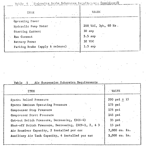
The air compressor is a two-stage V type assembly, and through two pressure switches, will maintain the air pressure between the 145-175 psi. When the air pressure reaches 175 psi, the compressor shuts down and the condensate pop-off valve will momentarily open to discharge accumulated moisture.
The air suspension system is controlled by three car-leveling valves, one mounted on the X-truck and two mounted on the Y-truck. The truck suspension air bags are installed between the truck suspension adapter and truck side frame, with the leveling valve installed to the truck suspension adapter and the leveling valve linkage attached to the side frame. Compression of the air bags will cause the level valve to open to pressure and expansion of the air bags will cause the level valve to vent.
The car is considered as having a three point suspension, with each point having a leveling valve. The four X-end air bags are cross connected to the single X-end leveling valve. At the Y-end, only the two left air bags are connected to the left leveling valve, while the right air bags are connected to the right leveling valve. Therefore, not only will all leveling valves maintain the car floor height at 39-inches above the rail head in the longitudinal (fore - and - aft) direction, but, the two Y-truck leveling valves will maintain the car level in the traverse (sideway) direction for any placement of passenger loads.
During normal train operation braking or deceleration is accomplished through the traction motors by dynamic braking. Dynamic braking occurs within the speed range between 4 MPH and 80 MPH. At speeds under 4 MPH the dynamic field has decayed and the friction braking system assumes control. In the event of dynamic braking failure, the friction braking system will be used at any train speed. The friction braking system consists of a hydraulic power, unit, mounted on the underside of each vehicle, which supplies hydraulic pressure to a brake caliper mounted on each axle. Isolation of an individual vehicle may be accomplished by a manual cutoff valve. Control of the friction braking system is accomplished through the master brake control valve. The valve responds to electrical signals received from the vehicle control systems to allow system pressure to flow to the brake calipers. The magnitude of the pressure is determined by electrical signals from the control system. The friction braking system works in connection with the wheel slip-spin detector system. If slippage of a wheel occurs, the slippage is detected by the vehicle control system which, in turn, signals the brake control valve to reduce brake pressure and reapply when slippage stops. This cycle is repeated until slippage control is obtained.
Each vehicle incorporates an electrically operated hydraulic parking brake. The system includes a manual override. The parking brake is applied to the X-end truck only.
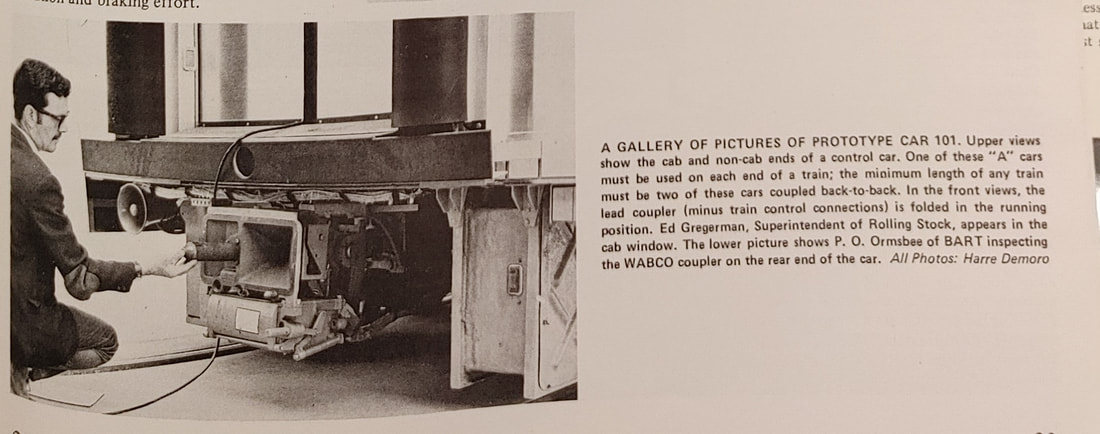
Car Coupler is a fully automatic car coupler, having a pin with a tapered point and a funnel at each coupling face. It is necessary only to bring two cars together at speeds from ¼ to 4 MPH to accomplish complete mechanical and electrical coupling. As the cars are brought together, the main coupling pin of each coupler head enters the funnel of the opposing coupler so long as the centerlines of the couplers are not misaligned by more than 6 inches laterally and 4 inches vertically. The main pin will align the heads within +-/- .012 inches and as coupling proceeds, secondary and tertiary alignment pins will engage to reduce, misalignment to +/- .0 inches: When the pins have completely entered the funnels, latches in each head snap into the notches in the main coupling, pins, thus locking the pins in the funnels.
The air connections from the uncoupling valve to the unlatching piston are made through the uncoupling hose and through the uncoupling air tappet on the coupler.
The electric portion includes a slide frame assembly and a removable front cover assembly. Each assembly includes 80 contacts with 30-amp capacity, and 58 contacts with 60-amp capacity.
The car coupling system provides the ability to couple cars mechanically and electrically without requiring any action on the part of the operator beyond controlling the rate of approach of the cars. Provisions are made to eliminate differences in coupler-to-coupler alignment in the vertical and horizontal direction and to eliminate the relative skewing that may exist between the coupler heads.
Uncoupling of cars is accomplished through an Uncoupling Valve located at either end of each car. An A-car is equipped with a manually operated valve mounted under the cab at the Y-end of the car and with a solenoid/manual operated valve at the X-end of the car and mounted to the right of the coupler,. A 13-char is equipped with two solenoid-piloted valves, one located at each end and mounted under the right side of the car.
The draft gear is designed to permit 1 1/2 inches travel at 150,000 pounds buff load, with a pre-load in each direction of 6,000 pounds. The draft gear assembly includes unique tensile bolts which break at 150,000 pounds, plus or minus 10%. Once released the draft gear has 3 1/2 inches collapsing travel to permit the car end to engage, causing the center, sill to absorb the additional loading.
The Retractable Coupler is designed to serve as a drawbar at the Y-end of A-cars. The assembly can be rotated a full 90 and locked in place under the car when not in use. Retraction is manual and uncoupling is accomplished with the manually operated uncoupling valve. No trainline electrical connections are provided. The Retractable Coupler can withstand buff and draft loads of 100,000 pounds.
Interior car lighting consists of 48 overhead lights in the passenger area, floor level lighting at all side and end doors and one standard overhead light and two variable overhead spot lights located in the Attendant's cab. Emergency power is provided by the battery circuit, the regular power source is the motor/alternator circuitry.
The BART vehicle is equipped with a communication network that provides intercommunications between units as follows:
1. INTERCOM - between a passenger and attendant.
2. Public Address (PA) - between attendant and all, passengers in the train.
3. Train Telephone (TT) - Radio telephone between attendant and
(a) Operating Control Center (OCC).
(b) Yard Control Station
(c) Mainline Relay Stations
4. Train Telephone PA (TPA) - Radio telephone to enable OCC or a Mainline Relay Station to transmit a public address announcement throughout a particular train. Each train has a separate radio frequency.
5. Attendant, Signal (ATT. SIG) -- Console handset communication between personnel in cabs at both ends of the train. (Primarily maintenance checkout personnel).

